I’ve been wearing a CGM for the last few months. One day I got curious. What does the inside of something you wear on your body for two weeks straight actually look like? So we tore it down.
Note that this is a third-party teardown, not our own product, we did not design or manufacture this device.
What is a CGM?
A CGM (Continuous Glucose Monitoring) is a wearable medical device used to track blood sugar levels 24/7 in real-time. It eliminates the need for finger-prick tests, by using a small sensor inserted just under the skin to measure glucose in the interstitial fluid. A CGM is basically the perfect hybrid between a medical and IoT (Internet of Things) device.
Some CGMs have real time transmission (through Bluetooth) to your phone, others need to be scanned by swiping the sensor with a device. More advanced ones can be implanted for 365 days monitoring and some are integrated with an automatically dosing insulin pump.
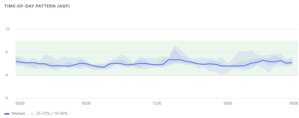
I started out using a swipe-type sensor, but the manual scanning got too tedious for my liking. I then upgraded to a Bluetooth model that streams to my smartphone. Seeing my own real-time biological data mapped out like this: as shown in my 24-hour AGP chart below; was a game-changer. It also gave me the perfect excuse to crack one open to see what’s inside.
The Device
The device splits into three functional groups: the top-half housing (launch mechanism and sensor mounting), the bottom-half housing (needle protector), and an accessories pack.
We’ll walk through each section in assembly order, noting material, wall thickness, and where warranted what we’d change if we owned this build. Material identifications below are suspected from visual and tactile cues. Wall thicknesses are measured values from CT scan data, +/- 0.01mm
Top-Half Assembly: The Launch Mechanism
Bottom Casing Lock — Suspected ABS, 0.9–1mm wall. This is a standalone fastening part whose function is locking the bottom casing shut. It’s a clean example of a part that exists because of a joining decision made upstream, not because the function demands it. If the top and bottom casings were designed with internal threads instead, this part disappears entirely — one less mold, one less pick-and-place step, one less failure point in the fastening chain. This is the single clearest part-count reduction opportunity in the whole assembly, and it recurs later.
PCB/Sensor — Two materials in one sub-assembly: a suspected ABS/PP body and an acrylic layer, joined by what appears to be adhesive. The skin-adhesive layer performs well — strong adherence is evident. Mixed-material joining via adhesive (rather than mechanical fastening or overmolding) is a defensible choice here given the thinness of the acrylic layer, but it’s worth flagging as a bonded joint with no visible mechanical backup — a single point of adhesive failure.
PCB/Sensor Base — This is a two-piece part: a top surface (1–2mm) that the PCB/sensor sits on, and a bottom surface (1.4–1.7mm) that houses the launch mechanism. Functionally these are two different jobs bolted into one component name, but structurally there’s no reason they need to be molded as two pieces. Combining top and bottom into a single part is a straightforward simplification — fewer mold cavities, fewer assembly steps, less risk of misalignment between the two halves during assembly.
Sensor Launch Spring — Steel, 1.4mm. This does double duty: driving the launch mechanism and mechanically retaining the PCB/sensor base in position. It’s a well-executed, low-part-count solution — the kind of component that doesn’t need a redesign note because it’s already doing two jobs with one part.
Top Casing — Suspected ABS, 2.4–2.8mm, and the most structurally complex part in the top half — it houses the entire launch mechanism and the related plastic sub-parts. Three things stand out here. First, there’s limited clearance for a user’s finger to flick the lid open — a usability constraint that shows up as a manufacturing constraint too, since tight clearances mean tighter tolerance requirements on the surrounding features. Second, there’s no visible poka-yoke (foolproofing) geometry to prevent incorrect assembly orientation — worth adding given how many sub-parts nest into this casing. Third, the same internal-threading opportunity from the Bottom Casing Lock applies here: an internal thread on the top casing could eliminate the separate locking part altogether.
Needle Base — Suspected PP, 1.2mm at the needle base, produced via insert molding around the needle itself. This is straightforward, logical design: insert-molding the needle directly into its base eliminates a secondary joining step and guarantees concentricity between needle and base. No suggestion here — it’s already efficient.
Launch Button Sub-Assy — Suspected ABS, 0.9–1mm. A simple, effective mechanism for actuating the launch. No design objection.
Lid for Launch Button — ABS, 1.5mm. Does its job — protecting the button from accidental actuation — with a simple geometry. The one gap: no poka-yoke feature to enforce correct orientation during assembly, which is a low-cost addition given the part’s simplicity.
Bottom-Half Assembly: The Needle Protector
Needle Protector (Case) — A two-material part: TPU (2.4–3.5mm) for the body and acrylic (0.7mm) for a window. The material logic is sound — TPU provides an assembly-friendly, puncture-safe barrier against the sharp needle end, while the acrylic window keeps the needle visible for user confidence before deployment. The one refinement opportunity: tighter, more uniform control of the diameter opening would let the TPU locking boss shrink and normalize to nominal wall thickness, reducing material variability at that interface.
Needle Protector Base — Suspected ABS or mixed plastics, 1.3–1.5mm. Functionally sound as the mounting base for the protector, but — as with the top-half casing lock — this part exists largely because of how the assembly is structured rather than because the function strictly requires a separate piece.
Bottom Casing — Suspected ABS, 1.8–2.4mm. This is more complex than it needs to be, and the complexity traces directly back to accommodating the needle protector base as a separate part. Flatten the bottom surface to reduce depth, extend the ribs on the bottom casing so the needle protector can seat directly on them, and the standalone needle protector base becomes unnecessary. The undercut area currently required for the base adds both part complexity and cost — removing it is a direct cost lever, not just a tidiness improvement.
Accessories Pack
Two vacuum-formed parts — top and bottom casing, suspected/confirmed polystyrene, 0.9–1.0mm wall — housing the device accessories. Assembly fit is good and the design is appropriately simple for a low-cost, non-critical enclosure. No changes warranted.
Synthesis: Where the Real Opportunity Sits
Across both halves, the same pattern repeats three times: a separate locking or base part exists to solve a joining problem that better casing geometry could solve directly. Internal threading on the top and bottom casings would eliminate the bottom casing lock entirely. Extended ribs on the bottom casing would eliminate the standalone needle protector base.
Combining the PCB/sensor base’s top and bottom surfaces into one mold would eliminate a second cavity and an alignment step. None of these are exotic fixes — they’re standard design for assembly: every eliminated part is one fewer mold, one fewer handling step, and one fewer place for tolerance stack-up to cause a failed snap-fit or misaligned launch mechanism.
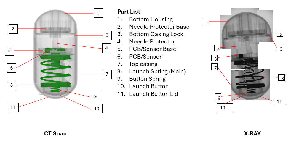
What made this CGM teardown possible without cutting the device apart destructively — and therefore without destroying the very assembly sequence we were trying to understand — was internal imaging at Allied Hori. We mapped this entire part list and assembly order, including the launch spring position and the needle protector nesting, using CT scan and X-ray before physical disassembly.
For contract manufacturing DFA work, that distinction matters: destructive teardown tells you what parts exist, but non-destructive imaging tells you how they were actually assembled, in what order, and where the tolerance risk sits: which is the information you need to redesign, not just describe